4Bit Relay Adder
Lessons Learned
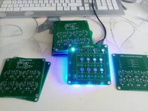
- Make the LED indicators from Cupper!!! Green soldermask is really transparent!
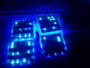
- Use blue or white soldermask with blue LEDs
- Make the signal connections on the front of the adder. This assists the understanding better.
- Use the mounting screws for power supply.
Status
09.Nov 2021
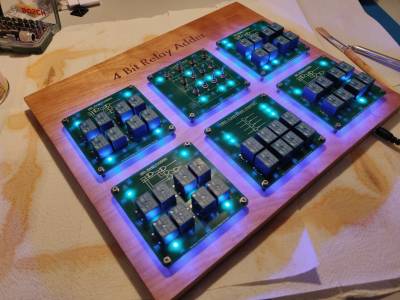
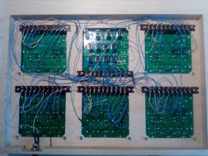
Finally added the transparent plexi backboard, the diodes and also oiled the wood. The project is finally finished.
23.Oct 2021
The sky blue version is ugly, so I bought a new one in transparent. This looks nice. Also I finally found time to put some oil on the wood. This also looks nice. The project is finished now and I am happy with it. Will upload images later.
03.Oct 2021
Finally I just ordered the plexi backboard in sky blue. I hope it looks nice.
11.May 2020
04.May 2020
27.Mrz 2020
21.Mrz 2020
I finished the integration test and everything works as intended. :) I'm out of LEDs now but new ones are in delivery. The whole thing looks very nice now! Hope I can produce the backboard soon when all the hackerspaces are open again after this corona thingy.
20.Mrz 2020
Remaining boards assembled. Waiting for the remaining 50 LEDs and 40 Diodes to finish the boards. Because of the current corona-crisis all the maker and hackerspaces are closed, so i won't find a place to build the backboard and finish the project in the next 5 weeks. :(
19.Mrz 2020
17.Mrz 2020
15.Mrz 2020
13.Mrz 2020
29.Feb 2020
PCBs are in delivery
27.Feb 2020
The PCBs are in production and all the main parts, to check the functionality, are ordered on Aliexpress.
Related Work
Media
Preface
This project is basically just a preproject for the EuroTwo CPU I'm currently working on. The plan for this project is to checkout how the design might look and how tiny I can get the boards. Also the connectors are of interest. Because there will be many wires in the back of the EuroTwo CPU which I will have to wire by hand I have to optimize the process and the connectors for them. There are many things to learn before starting with the bigger EuroTwo CPU.
Introduction
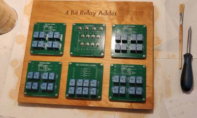
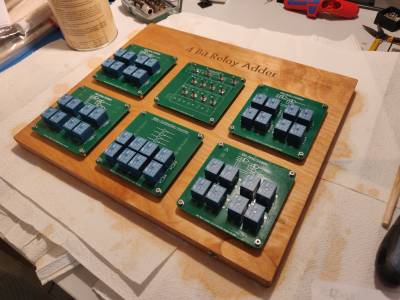
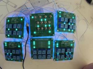
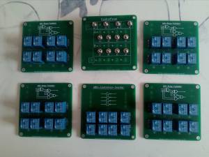
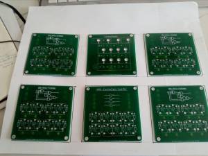
The goal is to build a 4Bit-Adder from relays. Therefore 4 PCBs with a 1Bit-FullAdder each are connected to one PCB with a 4Bit-Controlled-Inverter. Also I build a PCB containing the control switches for the inputs etc.. This board, called ControlPanel, is also displaying the output of the calculation. The PCBs are connected via soldered wires behind the visible front of the project. Each board has a backlight of 12 LEDs (3 per side).
This project will use 40 relay of the typ SRD-FormC (SPDT) and up to 150 LED for the backlight and the indication of states.
Logic
This project uses the following states:
| Logic | Electronic |
|---|---|
| Low (0) | floating |
| High (1) | +5V |
Gates
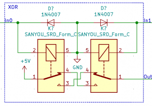
XOR
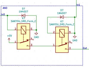
AND
I know I can build an AND gate from one relay. But in this preproject I build it from two. It is easy to explain how it works this way.
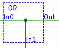
OR
The OR gate is very simple. As High is 5V and Low is floating we can just connect the wires to get the or logic.
Complete
The FullAdders works like this:
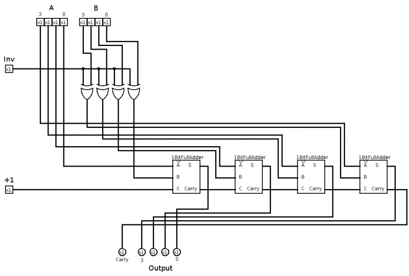
The boards will be connected to realize the following circuit:
A controlled inverter is the same as a XOR in my project. I know there are different understandings for this part.
TechDraw PCBs
Functional Schematic
In the following schematic I have documented how the project is working. It is clear that the real PCBs contain much more components like LEDs, Resistors, Caps and connectors. This schematic is a simplification.
Functional schematic rev1 [PDF]
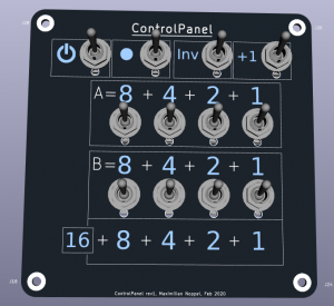
ControlPanel
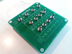
The controlpanel contains switches to give the following inputs:
- On/Off-Switch for the complete project
- Reserved-Switch
- Enable-Inverter-Switch
- Enable-Plus1-Switch
- 4 Inputswitches for A
- 4 Inputswitches for B
The Enable-Inverter-Switch and Enable-Plus1-Switch enable the user to substract by using the two's-complement. Thus it is a 4Bit-Adder and a 4Bit-Substractor.
Each switch has a LED-indication of it's state.
The result is displayed in 5 bits, including the Carry-Bit (as „16“) of the FullAdder.
Schematic
BOM
| Designator | Package | Quantity | Designation |
|---|---|---|---|
| D29,D1,D2,D3,D4,D5,D6, D7,D9,D10,D11,D12,D13, D14,D15,D16,D17,D18,D19,D20, D22,D23,D24,D25,D26, D27,D8,D21,D28 | LED_1206_3216 | 29 | blue at 16mA, 5V |
| R29,R1,R2,R3,R4,R5,R6,R7, R9,R10,R11,R12,R13,R14, R15,R16,R17,R18,R19,R20,R22, R23,R24,R25,R26,R27, R8,R21,R28 | R_0603_1608 | 29 | 330R |
| C1,C2 | CP_Elec_6.3×5.4 | 2 | 47uF |
| C3,C4,C5 | C_0805_2012 | 3 | 100nF |
| SW1,SW2,SW3,SW4,SW5,SW6,SW7,SW8, SW9,SW10,SW11,SW12 | MST-102 | 12 | MST-102 |
Lessons Learned
- Use just one switch to switch to the substractor-mode
- Build an alternative display mode for the substractor. Which is active depending on the one sub-switch. In this case Out_3 is the sign bit and should be displayed as „-“. This will require some more relays.
1Bit-FullAdder
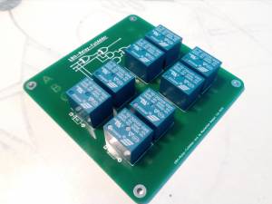
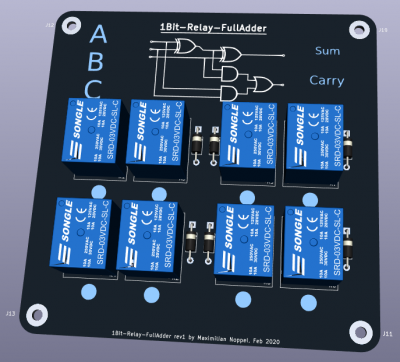
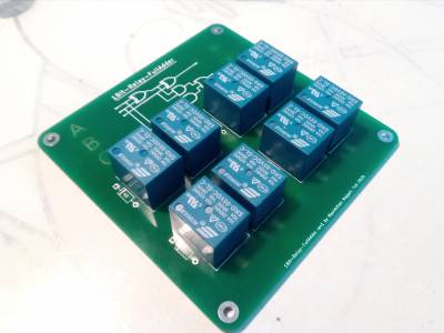
The 1Bit-FullAdder sums 3 (A,B,C) inputs and outputs a sum bit and a carry bit.
Therefore 8 relays are used. For details see the schematic.
Schematic
BOM
| Designator | Package | Quantity | Designation |
|---|---|---|---|
| D7,D11,D12,D10,D6,D9,D4,D5 | D_A-405_P10.16mm_Horizontal | 8 | 1N4007 |
| R30,R2,R17,R23,R32,R3,R1, R13,R29,R21,R20,R26,R16,R14, R8,R18,R25,R15,R24,R31, R5,R28,R27,R19,R22,R9 | R_0603_1608 | 25 | 330R |
| D14,D13,D18,D29,D21,D30, D16,D25,D22,D24,D33,D34,D2,D8, D20,D31,D3,D23,D28,D26,D32, D17,D19,D27,D15 | LED_1206_3216 | 25 | blue with 16mA, 5V |
| R4,R6,R7,R10,R11,R12 | R_0603_1608 | 6 | not mounted |
| C1,C2 | CP_Elec_6.3×5.4 | 2 | 47uF |
| C3,C4,C5 | C_0805_2012 | 3 | 1000nF Keramik |
| K1,K2,K3,K4,K5,K6,K7,K8 | SRD-C | 8 | SANYOU SRD Form-C |
4Bit-Controlled-Inverter
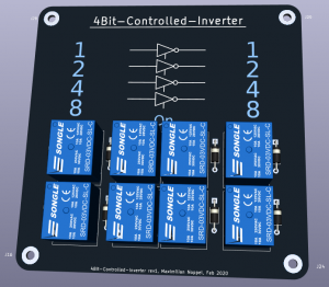
The 4Bit-Controlled-Inverter board is able to invert 4 bits. The board is enabled by the Enable-Inverter-Switch on the ControlPanel. It also indicates the input bits and the output bits by LEDs.
Schematics
BOM
| Designator | Package | Quantity | Designation |
|---|---|---|---|
| D1,D2,D3,D4,D5,D6,D7,D9, D10,D11,D12,D13,D14,D15, D16,D17,D18,D19,D20,D22,D31 | LED_1206_3216 | 21 | blue at 16mA, 5V |
| R1,R2,R3,R4,R5,R6,R7,R9, R10,R11,R12,R13,R14,R15, R16,R17,R18,R19,R20,R22,R21 | R_0603_1608 | 21 | 330R |
| C1,C2 | CP_Elec_6.3×5.4 | 2 | 47uF |
| C3,C4,C5 | C_0805_2012 | 3 | 100nF |
| D8,D21,D23,D24,D25,D26, D27,D28 | D_A-405_P10.16mm_Horizontal | 8 | 1N4007 |
| K1,K2,K3,K4,K5,K6,K7,K8 | SRD-C | 8 | SANYOU SRC-FormC |
Backboard
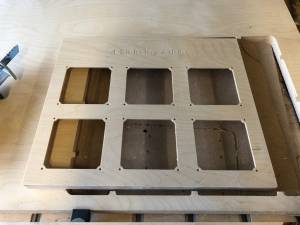
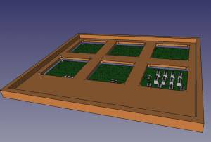
The backboard will be made from wood.
TechDraw:
—-
